Kinematic Self-Replicating Machines
© 2004 Robert A. Freitas Jr. and Ralph C. Merkle. All Rights Reserved.
Robert A. Freitas Jr., Ralph C. Merkle, Kinematic Self-Replicating Machines, Landes Bioscience, Georgetown, TX, 2004.
4.18 Freitas Biphase Assembler (2000)
Prior to his collaboration with Merkle (Section 4.11.3) during October 2000, Freitas sketched out a simple scaling study of a new molecular assembler architecture as a thought-experiment to demonstrate subunit specialization using individual replicator devices as an alternative to the more conventional specialized-subunit “factory production line” approach of Drexler’s desktop assembler (Section 4.9.3) and Hall’s factory replication architecture (Section 4.16). The biphase architecture also shows one way that the functions of fabrication and assembly performed by the Merkle-Freitas assembler (Section 4.11.3) could be separated into two distinct devices, possibly allowing faster operation and higher efficiency of the system as a whole although at the cost of some increased system complexity.
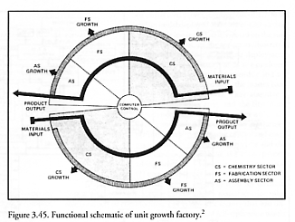
In the biphase assembler architecture, two classes of microscopic replicator devices cooperate in the manufacture of more replicator devices while freely suspended in a working fluid (either a liquid or a pressurized inert gas). Following Freitas’ 1980 lunar factory replication concept (Section 3.13.2.2) in which the factory is divided into chemical processing, fabrication, and assembly subsystems (Figure 3.45), the biphase assembler is composed of (1) a population of identical fabrication devices that manufacture parts from molecular feedstock and (2) a separate population of identical assembly devices that manufacture fabrication devices and assembly devices from parts produced by the fabrication devices. The fabrication devices can also manufacture some range of non-self parts and the assembly devices can assemble some range of non-self parts, so that the system can also manufacture some range of useful non-self products. Fabrication and assembly devices are of similar size, in the 0.2-0.5 micron range.
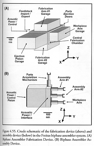
The fabrication device (Figure 4.55(A)) consists of a central fabrication chamber measuring 300 nm x 300 nm x 200 nm (in the X, Y, and Z directions). The left face of the chamber includes molecular feedstock import and waste export mechanisms (e.g., sorting rotors) and an acoustic power/control piston, and on the right face is attached a workpiece arm garage 125 nm deep. To the top and bottom faces of the chamber are attached a 125-nm deep fabrication arm garage for each of the two fabrication arms. The 150-nm deep parts ejection piston garage is attached to the front face of the chamber, and there are tight-sliding parts ejection doors on the rear face of the central chamber, hence the entire fabrication device will fit within a 450-nm cube.
During one cycle of operation, feedstock molecules solvated in the external fluidic environment are imported into the device and made available to two opposed mechanosynthetic fabrication arms which perform fabrication operations in a vacuum environment and can exchange and reuse tool tips stored in a recessed tooltip garage on the inside of the materials import wall. The workpiece is held in proper position and orientation by the workpiece arm. When fabrication of a part is complete, the two mechanosynthetic arms are retracted and stowed behind fluidtight doors, the tooltip garage is sealed off, the workpiece arm releases the part into the chamber interior and then stows itself behind fluidtight doors, the parts ejection doors open (flooding the interior with working fluid from the external environment), the parts ejection piston ejects all contents of the fabrication chamber (including flood fluids and the recently finished part) from the chamber, the ejection doors close tightly against the piston face, the ejection piston retracts (re-establishing a vacuum inside the fabrication chamber), and the fabrication device is ready for the next cycle of operation. Obviously the chamber interior must contain no ledges where a finished part could become wedged and prevent its own ejection, and numerous other practical design issues remain to be addressed (e.g., bakeout plus rotor-based getters might be needed to remove lingering contaminant fluid molecules from the chamber interior between each cycle; released finished parts must be chemically unreactive with feedstock molecules and working fluid; etc.). It is envisioned that a large population of fabrication devices residing in a microfluidic processing tank would manufacture a large batch of one type of part, after which the mixed population of devices and parts could be readily separated by physical filtration or gentle centrifugation with the pure fraction of finished parts shunted to inventory and the pure fraction of fabrication devices returned to the processing tank for the next cycle of operation, ready to produce more parts of the same or a different kind.
The assembly device (Figure 4.55(B)) consists of a large acoustic power/control piston in a (200 nm)3 box with 15 nm thick walls and a 100 nm throw, giving a power input up to ~3000 pW with 1 atm pulses at 10 MHz. A power/control interface 50 nm thick transmits power and control signals to: (1) a parts acquisition mechanism (possibly including a special parts capture jig at the end effector) on the top face of the assembly device, and (2) three manipulator mechanisms including two assembly arms and one workpiece arm, all 100 nm in length, whose bases are positioned at the points of an equilateral triangle on the right face of the assembly device. With all manipulator mechanisms fully extended the entire assembly device would fit within a box of approximate dimensions 200 nm x 350 nm x 300 nm in the X, Y, and Z directions. All assembly operations take place in the external fluidic environment, at a location separate from the operations of fabrication devices.
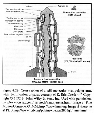
During one cycle of operation, a feedstock part in fluidic suspension is mechanically recognized and grasped by the parts acquisition mechanism, then presented at proper rotation to the two assembly arms which install the part into the growing workpiece held at proper rotation by the workpiece arm. The presence of three manipulator mechanisms makes possible mechanically complex assembly motions such as pin-insertion operations through two separate components whose holes must be simultaneously aligned. Because of the negligible mechanical influence of gravitational forces, the assembly device should be able to grip and manipulate a workpiece as large as itself or even somewhat larger, with crucial enabling design elements such as number and placement of workpiece surface gripholds and assembly device manipulator armlengths subject to design control. The assembly device installs new parts, one by one, on the growing workpiece. If each of the assembly arms is similar to Drexler’s fluidtight manipulator arm (Figure 4.29) and thus includes 49 parts (Section 4.9), and if we add an appropriate number of additional parts for end effectors, clutches, transmissions, odometers, power trains and the power/control piston assembly, and further assume 6 casing plates, then the assembly device is composed of a total of 430 parts and requires 429 assembly cycles to build a second assembly device. As with the fabrication devices, it is envisioned that a large population of assembly devices residing in a separate microfluidic processing vessel would first perform a large batch of one type of assembly operation in parallel, after which the mixed population of assembly devices with partially-completed workpieces attached and unused loose parts of one type floating in suspension would be separated by physical filtration or gentle centrifugation with the pure fraction of unused parts being returned to inventory and the pure fraction of assembly devices with attached workpieces being returned to the processing vessel, then mixed with a concentrated suspension of the next part type in the assembly sequence, in preparation for the next cycle of operation. Allowing 100 seconds per assembly cycle (including microfluidic separations) would give a replication time of ~0.5 day. (The fabrication device may possess up to twice as many parts and thus might require up to twice as many cycles for the assembly device to assemble it.)
The basic biphase assembler architecture could be further specialized by employing more than one class of fabrication or assembly device. In the limit of maximum specialization, using a separate class of fabrication device for each one of the many dozens of part types needed would allow each fabrication device to be optimized to achieve the most efficient manufacture of just one particular part type. Similarly, a separate class of assembly device could be used for each type of assembly joining operation that was required, essentially making assembly devices analogous to single-substrate enzymes in biology (e.g., “robozymes” or “mechanoenzymes”; Section 4.5). In principle, specialized assembly devices could perform covalent-bonding mechanosynthetic operations on parts to be joined, thus overcoming a key limitation of this architecture (viz., that fabricated parts must snap together during assembly in a fluid medium).
Last updated on 1 August 2005