Kinematic Self-Replicating Machines
© 2004 Robert A. Freitas Jr. and Ralph C. Merkle. All Rights Reserved.
Robert A. Freitas Jr., Ralph C. Merkle, Kinematic Self-Replicating Machines, Landes Bioscience, Georgetown, TX, 2004.
4.16 Hall Factory Replication System (1999)
Following in the intellectual lineage of the 1980 Freitas factory replication system (Section 3.13.2.2) and the 1991-1992 Drexler factory replication system (Section 4.9.3), in 1999 J.S. Hall published a general design [225] for a self-replicating molecular manufacturing system that is likewise composed of specialist machines, each one individually incapable of full self-replication but which can collectively fabricate and assemble all necessary components comprising all specialist devices within the system. Whereas the Freitas factory design employs three main classes of specialist production machines (i.e., chemical processors, parts fabricators, and parts assemblers [2, 1014]), and the Drexler factory design employs a succession of manipulators at increasingly larger scales (i.e., molecular fabricators, block assemblers, system assemblers [208, 2910]), the Hall factory design simplifies the number of specialist machines to just two – a parts fabricator and a parts assembler:
The parts fabricator has the following attributes:
The parts assembler, on the other hand, has these attributes:
The above architecture greatly simplifies the design of the fabricator because the objects it builds are rigid. This allows the fabricator to address reaction points on the surface of the partially-built product object without concern for whether the object has undergone a configurational change. It relieves the fabrication design process from the necessity of scaffolding, its provision and subsequent removal, simplifying the process and making it easier to maintain a eutactic environment. In the early stages, the system is assumed to be in a eutactic environment (possibly a non-reactive atmosphere). In later stages it may take on the task of extending the environment (e.g., with a balloon over the framework). Hall has described the components of his factory replicator in more detail:
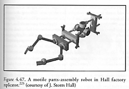
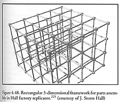
The parts assembler. The parts assembler consists of two elements – first, a parts-assembly robot (Figure 4.47) that is, except for its motility, consistent with the currently well-understood practice of parts-assembly robots; and second, a framework to move in (Figure 4.48) that provides precise positioning and traction (the problem of motion control is relatively modest). The salient features of the parts-assembly robot include its ability to engage, move, and turn in the framework, and the fact that it has two manipulators (although a judicious selection of jigs and clamps may obviate the duplication and permit a one-armed design). The outward clamps at the rear and near the geometric center of the robot engage the struts of the framework. This provides not only physical support but positional registration, as well as power and control signals. The earliest generations of these robots will have no onboard control but will obey signals transmitted across the framework. The framework itself is a simple rectangular 3-dimensional mesh, originally with conductive paths for only a single circuit. In the earliest generation, the entire framework is one interconnected multiconductor system. In subsequent generations, switching elements are built into the connectors and multiple conductive paths are incorporated into the struts. “Ultimately, the framework is a distributed control system coordinating the activities of large numbers of robots, as well as forming the physical infrastructure for the target product.” This would appear to restrict buildable products to those objects which can tolerate the permanent internal embedding of 3-dimensional electronic meshworks. Also, it is not clear from the discussion whether the parts fabricators and parts assemblers themselves incorporate such meshworks.
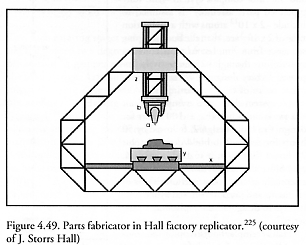
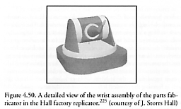
The parts fabricator. The parts fabricator (Figure 4.49) is loosely based on a conventional milling machine, with long motion axes all driven by lead screws and the motions of the wrist (Figure 4.50) to orient the working tip driven by high-reduction-ratio steppers with short working radii. The parts fabricator uses similar motor and control structures as the assembly robot, but these are arranged to deliver more precise (but thereby slower and shorter) positioning capability. In theory, a 4-position (2-phase) stepper with a 50-to-1 reduction driving a 2-nm pitch lead screw (i.e., 1-nm lands and 1-nm grooves) can position a slider with a precision of 0.01 nm (which is sufficient for mechanosynthesis), and the parts can be assembled correctly by a manipulator with only 0.10-0.25 nm precision. “A problem that does not appear to have been addressed to date is that of starting the deposition process. A possible approach would be ‘starting blocks,’ which would be small blocks of diamondoid material provided as raw material (just as working tips would be). The table (Figure 4.49) would be tessellated with cavities of an appropriate shape to bind the starting blocks reliably. Once the part had been fabricated, it would be removed from the table by the application of mechanical force by an assembly robot. The assembly robots would also position the starting blocks initially and provide the fabricator with a stream of working tips in early versions. (Note that self-assisted assembly,* together with appropriate jigs and limit stops, allows the robot to place the tool precisely in the synthesizer’s manipulator.) An openwork truss can have a high stiffness-to-mass ratio, and can be easily assembled from smaller parts. In this design (Figure 4.49), there are three axes of motion consisting of sliding dadoes driven by lead screws. There are three axes of orientation at the wrist for the mechanosynthetic active tip. The bend in the toolholder (Figure 4.50) allows a greater range of access to the typical object under construction than a straight one would.”
* Self-assisted assembly, like guided or directed self-assembly (Section 4.1.5), represents a halfway point between full positional assembly and full self-assembly – as for example, a screw which, when pressed to a hole and axially pushed forward, screws itself into the hole.
Another interesting aspect of Hall’s design is his concept of a pre-planned sequence for “iterated design bootstrapping.” Whereas bootstrapping had previously been considered in other contexts (Section 3.9) – for example, Freitas [1014] had advocated a basic two-step bootstrap in which a simple seed would build a complex factory, which factory would then build the desired large output product, a space probe (Section 3.11) – Hall [225] discussed a multi-step process that might be the optimal overall approach to bootstrapping replicators: “Suppose we have a series of designs, each some small factor, say 5.8, more complex, and some small factor, say 2, faster to replicate, than the previous. Then we optimally run each design 2 generations and build one unit of the next design. As long as we have a series of new designs whose size and speed improve at this rate, we can build the entire series in a fixed, constant amount of time no matter how many designs are in the series. (It’s the sum of an arbitrarily long series of exponentially decreasing terms – perhaps we should call such a scheme ‘Zeno’s Factory.’)” If the simplest possible factory replication “seed” system is assumed to be composed of ~107 atoms and requires ~105 sec for replication, and the most complex system “with fully pipelined parts assembly” is assumed to include ~2 x 10¹² atoms with a replication time of 2 x 10⁻³ sec, then the bootstrapping sequence from simplest to most complex system runs through ~25 successively improved factory designs. “With the appropriate series of designs starting from the simple system above, the asymptotic limit is a week and a half (e.g., ~100 hours for design 1 to build design 2, followed by 50 hours for design 2 to build design 3, plus 25 hours for design 3 to build design 4, etc.) Since all the designs need to be ready essentially at once, construction time is to all intents and purposes limited by the time it takes to design all the replicators in the series.”
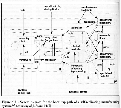
Hall’s exemplar bootstrapping sequence would start with “a small framework, one assembly robot, and a pile of parts,” and would progress through a series of four factory configurations, labeled “I” through “IV” in Figure 4.51. These would result in a more complex factory system differing dramatically from the first, with “each of the processes of the earlier stages taken over by specialized machinery. Pipelined processes (i.e., assembly lines) do the building, while pipes, conveyor belts, and, ultimately, vehicles do the moving. A fully-functioning fourth-stage system can discard everything that comprised the second stage system.”
Last updated on 1 August 2005