Kinematic Self-Replicating Machines
© 2004 Robert A. Freitas Jr. and Ralph C. Merkle. All Rights Reserved.
Robert A. Freitas Jr., Ralph C. Merkle, Kinematic Self-Replicating Machines, Landes Bioscience, Georgetown, TX, 2004.
B.4.2 Physical Description of Acoustic Transducer and Pressure Bands
Our proposed molecular assembler employs a single large acoustic transducer at the piston end wall. The transducer consists of three simple components: (1) a piston plate, (2) a piston rod, and (3) a piston spring.
The piston plate is a hydrogen-terminated diamond block measuring xpiston = 10 nm thick and with square cross-section of dimension Yint Zint, less four small square corner cutouts of dimension xvdWlegwidth2 = 100 nm2 each to accommodate the legs of the van der Waals cage (Section 4.11.3.4 (11)). Hence the piston plate area is Stransducer = Yint Zint - 4xvdWlegwidth2 = 2800 nm2. The piston plate slides in contact (and makes a tight seal) with the hydrogen-terminated diamond inner hull walls and extended legs of the van der Waals cage that projects outward from the piston end wall at the hull corners. The piston end wall includes four small inward-pointing 1-nm tabs on the hull to prevent the piston plate from exiting the assembler, should the external pressure ever fall below 1 atm (e.g., during storage between replication cycles).
The piston rod attached to the center of the inside face of the piston plate that extends back through the elevator plate to engage the control chain mechanism that is attached to the other side of the elevator plate, in the assembler interior. The piston rod is a hydrogen-terminated diamond rectangular solid rod measuring xrodwidth2 in cross-section and xrodlength = xpistonrod + xthrow + xelevator + xelevatorrod = 100 nm in length, where xrodwidth = 4 nm, xpistonrod = 64.286 nm, xthrow = 15 nm and xelevator = 10 nm, and xelevatorrod = 10.714 nm, the minimum distance the piston rod protrudes beyond the inwardmost face of the elevator plate. (The maximum protrusion above the elevator plate is xthrow + xelevatorrod = 25.714 nm.)
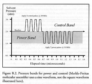
In normal operation, the assembler resides in a pressurized fluid environment. At the beginning of the replicative cycle, pressure is slowly raised to 4 atm to unlock and activate any new daughter devices that may be present. The pressure is then slowly lowered to the baseline pressure of 2.0 atm. Thereafter, fluid pressure is varied between Pmin = 1.0 atm and Pmax = 3.0 atm in two pressure bands, each band 1.0 atm wide. (The acetylene decomposition pressure in n-octane solvent is assumed to be 17 atm (Section B.4.1), which lies comfortably above Pmax.)
The piston spring is attached to the underside of the elevator plate at one end and to the piston rod at the other end. The spring ensures that the piston plate is at zero throw at <1 atm applied pressure, 5 nm throw at 2 atm, 10 nm throw at 3 atm, and 15 nm throw at >4 atm, and a 1-nm circumferential tab on the piston rod prevents its insertion more than 15 nm into the elevator plate, should the external pressure ever rise above 4 atm.
For any given control pulse, the probability qerr that the difference between two forces DF imposed on a piston that moves a distance L along its throw during a power stroke cannot be reliably distinguished from thermal noise [208] is given by qerr = exp (-L DFmin / 4 kT). Taking qerr = 10-15 to ensure a 99% probability of successful completion of a 1013-pulse command sequence at T = 273.15 K, and L = Lcontrol = 5.00 nm for each piston control band, then a power stroke force of DFmin = 104 pN must be applied in the control band to ensure adequate discrimination of piston pulses from thermal noise, representing a required minimum acoustic control pulse energy of DEmin = 521 zJ (~138 kT).
During single-band operation, the Gibbs free energy per power stroke is DGpiston = DPpiston DVpiston, where the pressure change across the control band is DPpiston = DPcontrol = 1.013 x 10⁵ N/m2 (1 atm) and the change in piston volume across the control band is DVpiston = DVcontrol = Lcontrol Stransducer = 14,000 nm3. This confirms that DGpiston = DGcontrol = DPcontrol DVcontrol = 1418 zJ (~376 kT per single-band power stroke) > DEmin and that the power stroke force of DFpiston = DFcontrol = DGcontrol / Lcontrol = 284 pN > DFmin = 104 pN. The required piston spring constant is kpistonspring = DFcontrol / Lcontrol = 0.0567 N/m (56.7 pN/nm). An excursion by the piston across a control band (5 nm of travel) in one half-cycle at nacoustic = 10 MHz gives a mean piston sliding speed of vpiston = 0.1 m/sec. The total power supplied to the device during single-band operation is therefore passembler = DFcontrol vpiston / 2 = 14.2 pW continuous, including the unpowered return stroke.
During double-band operation, we have DPpiston = 2DPcontrol = 2.026 x 10⁵ N/m2 (2 atm), Lpiston = 2Lcontrol = 10.00 nm, DVpiston = 2DVcontrol = 28,000 nm3, hence DGpiston = 4DGcontrol = 5673 zJ (~1503 kT per double-band piston stroke), piston force DFpiston = 2DFcontrol = 568 pN, and mean piston sliding speed vpiston = 0.2 m/sec at 10 MHz. Hence the total power supplied to the device during double-band operation is passembler = DFpiston vpiston / 2 = 56.8 pW continuous, including the unpowered return stroke.
The acoustic waveform used to drive the acoustic transducer is a 10 MHz sine wave of amplitude 1-2 atm or 2-3 atm in single-band operation, or 1-3 atm in double-band operation, depending upon which control response is desired. Reddy et al [3154] describe an AT-cut planar quartz crystal 160 microns thick that is driven in the thickness-shear-wave mode to produce 10 MHz (fundamental resonance frequency) longitudinal pressure waves in liquid n-octane or in liquid water. Unlike the square waves illustrated in Figure B.2, pure sine waves have no higher-frequency components. However, a transition from a sine wave of one amplitude to a sine wave of another amplitude, or a transition between a flat pressure regime and a sinusoidally varying pressure regime, can generate higher-frequency acoustic components that must be accounted for. In a practical system, the piston only sees the top portions of each sinusoidal pulse because the mechanism has a minimum pressure threshold for response, in excess of thermal noise.
Last updated on 13 August 2005