Kinematic Self-Replicating Machines
© 2004 Robert A. Freitas Jr. and Ralph C. Merkle. All Rights Reserved.
Robert A. Freitas Jr., Ralph C. Merkle, Kinematic Self-Replicating Machines, Landes Bioscience, Georgetown, TX, 2004.
3.4 Jacobson Locomotive Toy Train Replicator (1958)
In 1958, Homer Jacobson [687], a physicist at Brooklyn College in New York, was considering how one might build a self-replicating machine using electromechanical components. He started by noting that the essentials in a kinematic self-replicating system are: (1) an environment in which random elements, or parts, circulate freely; (2) an adequate supply of prefabricated parts; (3) a usable source of energy for assembly of these parts; and (4) a pre-assembled seed replicator, composed of the available parts, capable of taking those parts from the environment and synthesizing them into a functional copy of its own assembly, using the available energy to do so. The first design that occurred to Jacobson was “a simple mechanical self-assembler, consisting of motor, plan, and sensor. Under control of the plan, the motor could move the sensor about a junkyard-like environment of parts, pick up the proper part, move it to some nearby assembly area, and perform any necessary assembly operations. The chief difficulty with designing such a model is in designing a motor which operates on parts at a distance, picks up a copy of itself, and drops it into an accurately positioned spot at some like distance. This difficulty of designing a motor to move all the parts could be eliminated by allowing the parts to move under their own power, i.e., be locomotive.”
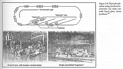
Working from this insight, Jacobson built a self-replicating device using modified parts from an HO train set (photographs of the actual working models have been published; Figure 3.9). In Jacobson’s “Reproductive Sequence Device One” or RSD1, there are two kinds of programmed, self-propelled toy train engines, called heads and tails, that circulate individually in random sequence around a loop of track with several sidings (Figure 3.9). With the sidings empty, nothing happens. But if an ordered pair of engines, a head (A) and tail (B), comprising the replicator, is once assembled on a siding, then this replicator can cause more copies of itself to be assembled on adjacent sidings. This is simply accomplished as follows. First, the head car in the pair waits for a free head car to come by and, upon detecting it, orders the tail car to open a switch that shunts it onto the adjacent open siding. In similar manner, the next free tail car to come by is shunted onto that same siding to make a new head-tail pair. Once this happens the first toy engine couple turns itself off and the second pair becomes the active replicator. Replication continues to propagate in linear fashion “until the environment runs out of parts, or there are no more sidings available, or a mistake is made somewhere in the operation of a cycle.” Note that a great deal of functionality essential for replication resides in the environment, including the spacer system, siding end stops, and motor cutoffs.
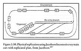
A more sophisticated device, the RSD4, would allow both the duplication of a replicator according to a set of plans in the parent, but also would allow for the duplication of the plans during replication, in keeping with the von Neumann kinematic motif. In the RSD4 (Figure 3.10), which was designed but apparently never built, the replicator now consists of three toy engines – a head (A), body (B), and tail (C). Heads and tails circulate freely as before, but there is only one body, containing the plan, in the replicator. Tail and body toy engines are identical, except the former contains an unpunched card, which, upon being punched with the plan, is converted to a body car that is released back into the environment via the re-entry branch of track.
Last updated on 1 August 2005