Kinematic Self-Replicating Machines
© 2004 Robert A. Freitas Jr. and Ralph C. Merkle. All Rights Reserved.
Robert A. Freitas Jr., Ralph C. Merkle, Kinematic Self-Replicating Machines, Landes Bioscience, Georgetown, TX, 2004.
List of Figures
Preface
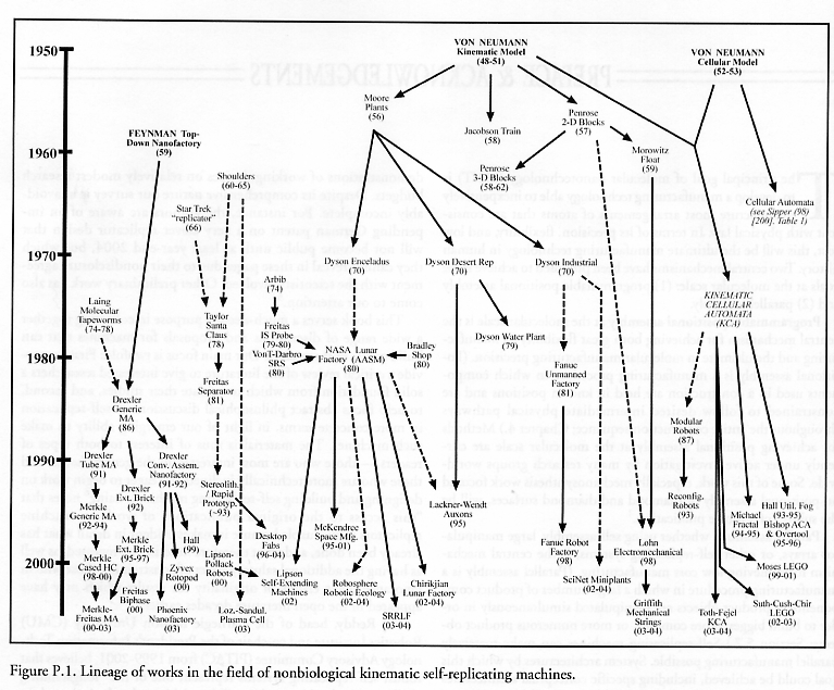
Figure P.1. Lineage of works in the field of nonbiological kinematic self-replicating machines...20
Chapter 1. The Concept of Self-Replicating Machines
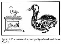
Figure 1.1. Vaucanson’s duck...26
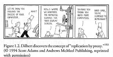
Figure 1.2. Dilbert discovers the concept of “replication by proxy”...28
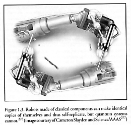
Figure 1.3. Robots made of classical components can make identical copies of themselves and thus self-replicate, but quantum systems cannot...33
Chapter 2. Classical Theory of Machine Replication
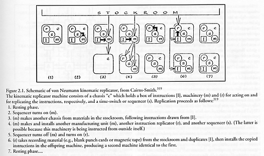
Figure 2.1. Schematic of von Neumann kinematic replicator...39
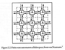
Figure 2.2. Finite state automaton cellular space...41
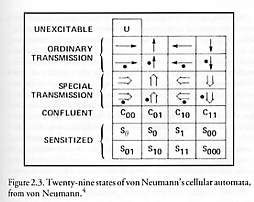
Figure 2.3. Twenty-nine states of von Neumann’s cellular automata...42
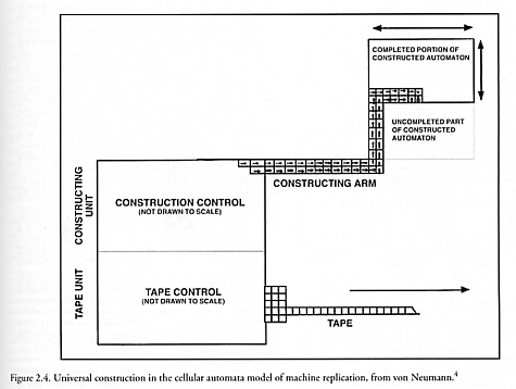
Figure 2.4. Universal construction in the cellular automata model of machine replication...43
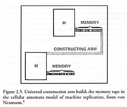
Figure 2.5. Universal construction arm builds the memory tape in the cellular automata model of machine replication...44
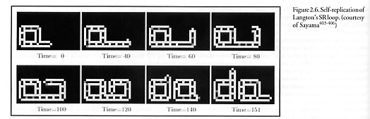
Figure 2.6. Self-replication of Langton’s SR loop...48
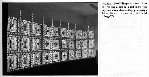
Figure 2.7. BioWall implementation showing genotypic data path and phenotypic representation of Swiss flag...51
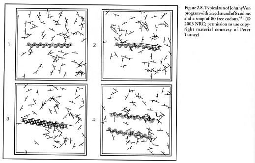
Figure 2.8. Typical run of JohnnyVon program with a seed strand of 8 codons and a soup of 80 free codons...53
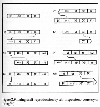
Figure 2.9. Laing’s self-reproduction by self-inspection...57
Chapter 3. Macroscale Kinematic Machine Replicators
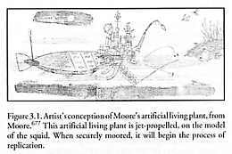
Figure 3.1. Artist’s conception of Moore’s artificial living plant...62
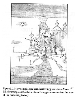
Figure 3.2. Harvesting Moore’s artificial living plants...63
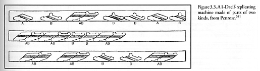
Figure 3.3. A 1-D self-replicating machine made of parts of two kinds...65
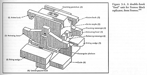
Figure 3.4. A double-hook “food” unit for Penrose block replicator...66
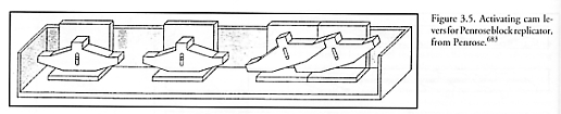
Figure 3.5. Activating cam levers for Penrose block replicator...66
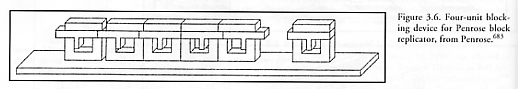
Figure 3.6. Four-unit blocking device for Penrose block replicator...67
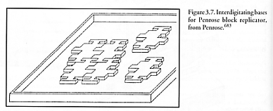
Figure 3.7. Interdigitating bases for Penrose block replicator...67
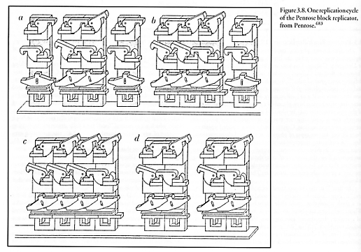
Figure 3.8. One replication cycle of the Penrose block replicator...68
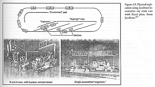
Figure 3.9. Physical replication using Jacobson locomotive toy train cars with fixed plan...69
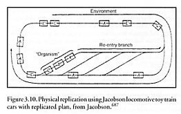
Figure 3.10. Physical replication using Jacobson locomotive toy train cars with replicated plan...70
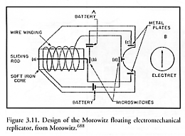
Figure 3.11. Design of the Morowitz floating electromechanical replicator...71
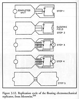
Figure 3.12. Replication cycle of the floating electromechanical replicator...71
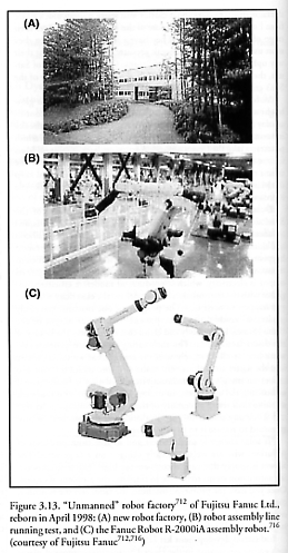
Figure 3.13. “Unmanned” robot factory of Fujitsu Fanuc Ltd., reborn in April 1998...76
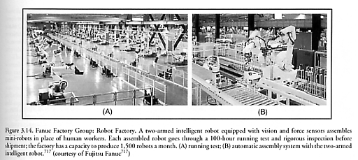
Figure 3.14. Fanuc Factory Group: Robot Factory...76
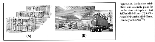
Figure 3.15. Production mini-plants and assembly plant for production mini-plants...79
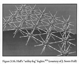
Figure 3.16. Hall’s “utility fog” foglets...81
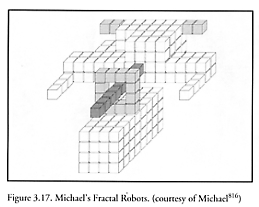
Figure 3.17. Michael’s Fractal Robots...82
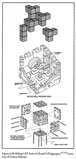
Figure 3.18. Bishop’s XY Active Cell and Cell Aggregate...84
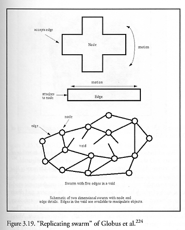
Figure 3.19. “Replicating swarm” of Globus et al...84
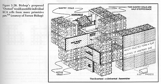
Figure 3.20. Bishop’s proposed “Overtool” would assemble individual KCA cells from more primitive parts...85
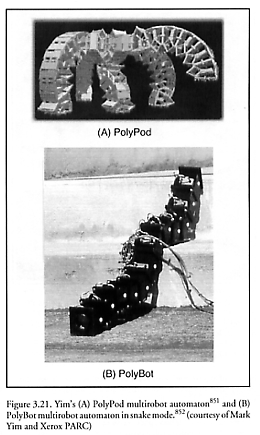
Figure 3.21. Yim’s (A) PolyPod multirobot automaton and (B) PolyBot multirobot automaton in snake mode...86
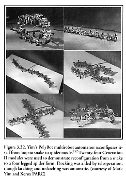
Figure 3.22. Yim’s PolyBot multirobot automaton reconfigures itself from loop to snake to spider mode...87
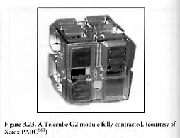
Figure 3.23. A Telecube G2 module fully contracted...88
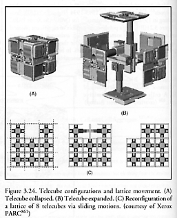
Figure 3.24. Telecube configurations and lattice movement...88
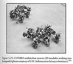
Figure 3.25. CONRO multirobot system (20 modules making two hexapods)...89
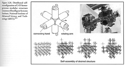
Figure 3.26. Distributed self-reconfiguration of 3-D homogeneous modular structure...90
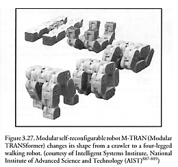
Figure 3.27. Modular self-reconfigurable robot M-TRAN (Modular TRANSformer) changes its shape from a crawler to a four-legged walking robot...91
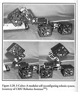
Figure 3.28. I-Cubes: A modular self-reconfiguring robotic system...92
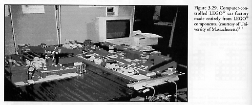
Figure 3.29. Computer-controlled LEGO® car factory made entirely from LEGO® components...93
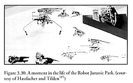
Figure 3.30. A moment in the life of the Robot Jurassic Park...95
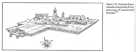
Figure 3.31. Automated space manufacturing facility for the processing of nonterrestrial materials...98
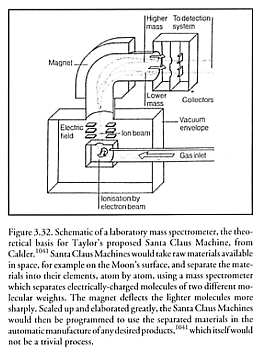
Figure 3.32. Schematic of a laboratory mass spectrometer, the theoretical basis for Taylor’s proposed Santa Claus Machine...99
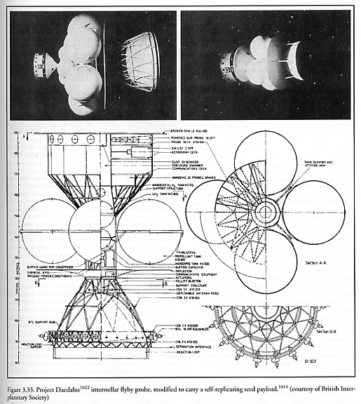
Figure 3.33. Project Daedalus interstellar flyby probe, modified to carry a self-replicating seed payload...102
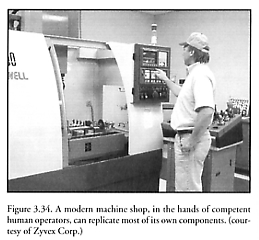
Figure 3.34. A modern machine shop, in the hands of competent human operators, can replicate itself...104
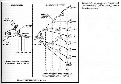
Figure 3.35. Comparison of “linear” and “exponentiating” (self-replicating) manufacturing systems...109
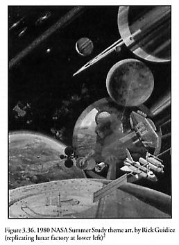
Figure 3.36. 1980 NASA Summer Study theme art...110
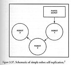
Figure 3.37. Schematic of simple robot self-replication...113
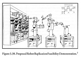
Figure 3.38. Proposed robot replication feasibility demonstration...114
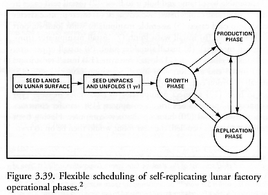
Figure 3.39. Flexible scheduling of self-replicating lunar factory operational phases...116
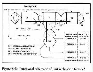
Figure 3.40. Functional schematic of unit replication factory...117
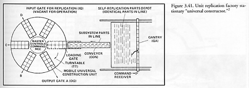
Figure 3.41. Unit replication factory stationary “universal constructor”...118
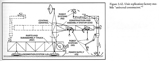
Figure 3.42. Unit replication factory mobile “universal constructor”...119
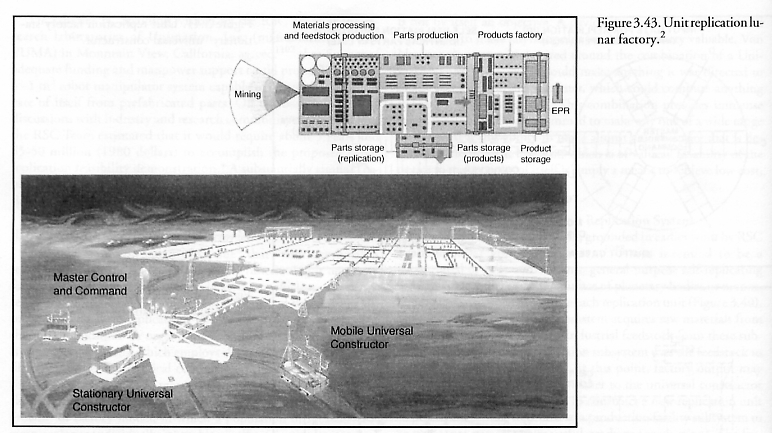
Figure 3.43. Unit replication lunar factory...120
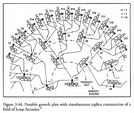
Figure 3.44. Possible growth plan with simultaneous replica construction of a field of lunar factories...121
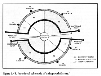
Figure 3.45. Functional schematic of unit growth factory...122
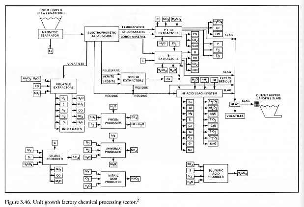
Figure 3.46. Unit growth factory chemical processing sector...123
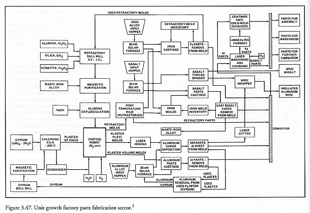
Figure 3.47. Unit growth factory parts fabrication sector...124
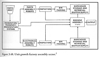
Figure 3.48. Unit growth factory assembly sector...125
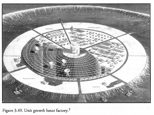
Figure 3.49. Unit growth lunar factory...126
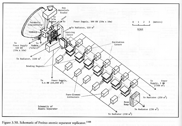
Figure 3.50. Schematic of Freitas atomic separator replicator...127
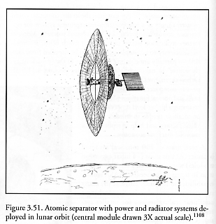
Figure 3.51. Atomic separator with power and radiator systems deployed in lunar orbit...128
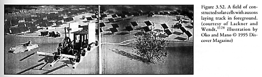
Figure 3.52. A field of constructed solar cells with auxons laying track in foreground...129
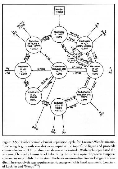
Figure 3.53. Carbothermic element separation cycle for Lackner-Wendt auxons...130
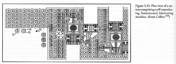
Figure 3.54. Plan view of a system comprising a self-reproducing fundamental fabricating machine...131
Figure
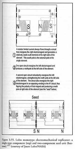
3.55. Lohn monotype electromechanical replicator: a single-type component
and two-component seed unit...140
Figure
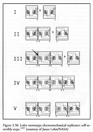
3.56. Lohn monotype electromechanical replicator: self-assembly steps...141
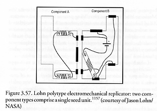
Figure 3.57. Lohn polytype electromechanical replicator: two component types comprise a single seed unit...142
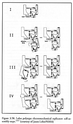
Figure 3.58. Lohn polytype electromechanical replicator: self-assembly steps...143
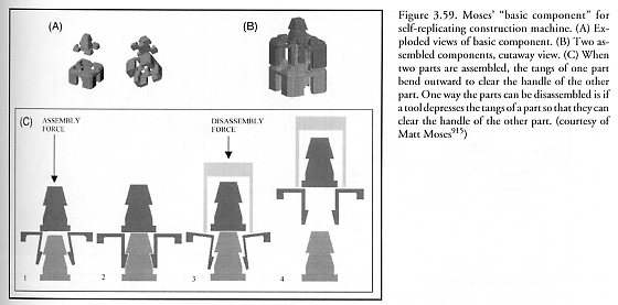
Figure 3.59. Moses’ “basic component” for self-replicating construction machine...144
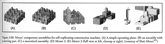
Figure 3.60. Moses’ component assemblies for self-replicating construction machine...145
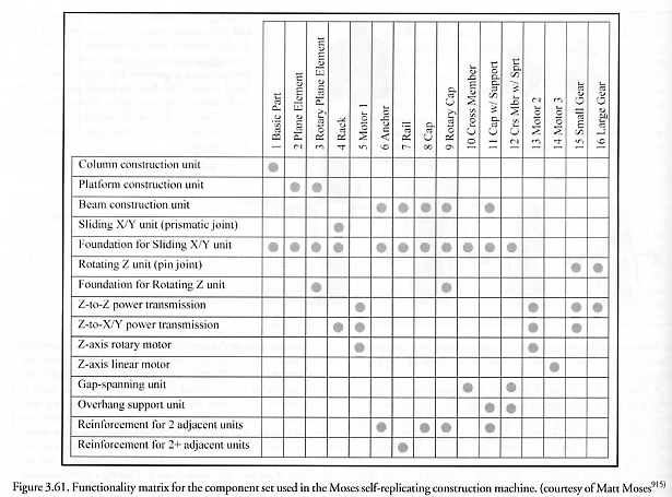
Figure 3.61. Functionality matrix for the component set used in the Moses self-replicating construction machine...146
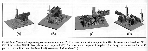
Figure 3.62. Moses’ self-replicating construction machine...147
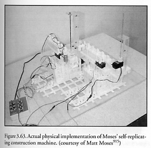
Figure 3.63. Actual physical implementation of Moses’ self-replicating construction machine...148
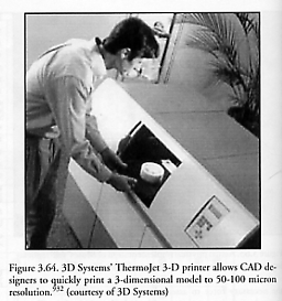
Figure 3.64. 3D Systems’ ThermoJet 3-D printer allows CAD designers to quickly print a 3-dimensional model to 50-100 micron resolution...151
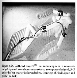
Figure 3.65. GOLEM Project uses robotic system to automatically design and manufacture new robots...152
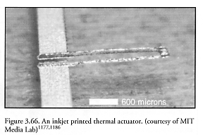
Figure 3.66. An inkjet printed thermal actuator...154
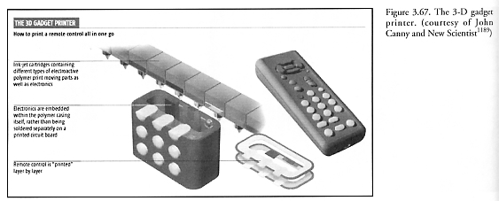
Figure 3.67. The 3-D gadget printer...154
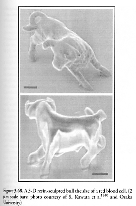
Figure 3.68. A 3-D resin-sculpted bull the size of a red blood cell...157
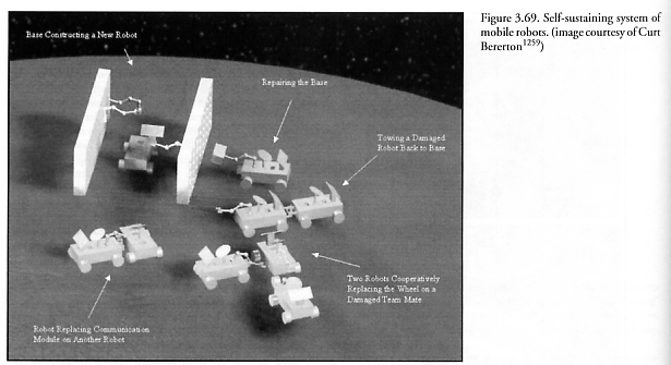
Figure 3.69. Self-sustaining system of mobile robots...158
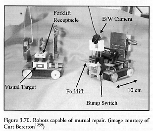
Figure 3.70. Robots capable of mutual repair...159
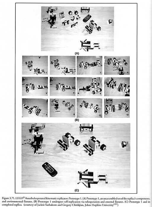
Figure 3.71. LEGO®-based teleoperated kinematic replicator: Prototype 1...162
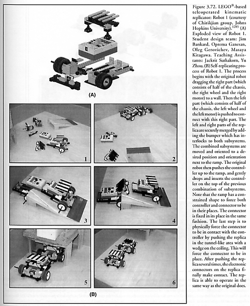
Figure 3.72. LEGO®-based teleoperated kinematic replicator: Robot 1...164
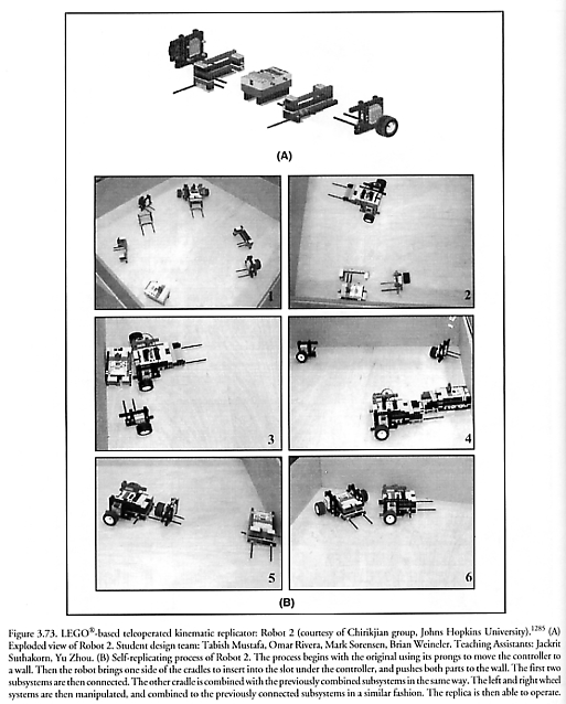
Figure 3.73. LEGO®-based teleoperated kinematic replicator: Robot 2...166
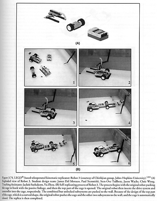
Figure 3.74. LEGO®-based teleoperated kinematic replicator: Robot 3...167
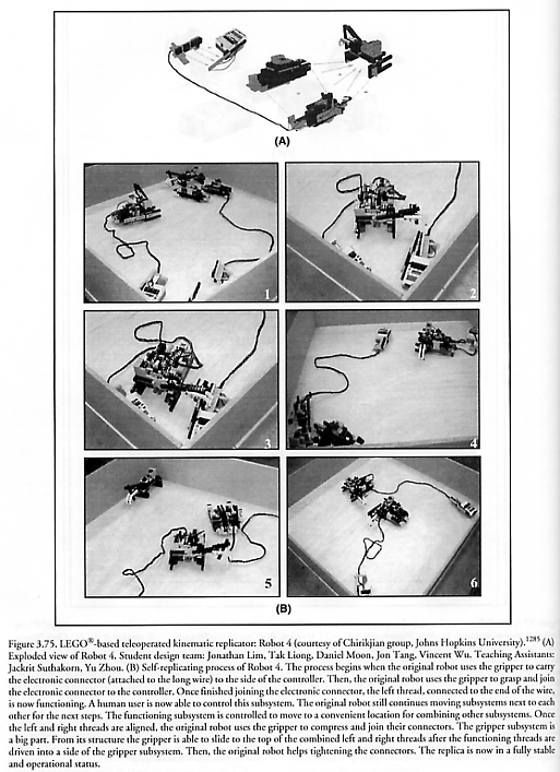
Figure 3.75. LEGO®-based teleoperated kinematic replicator: Robot 4...168
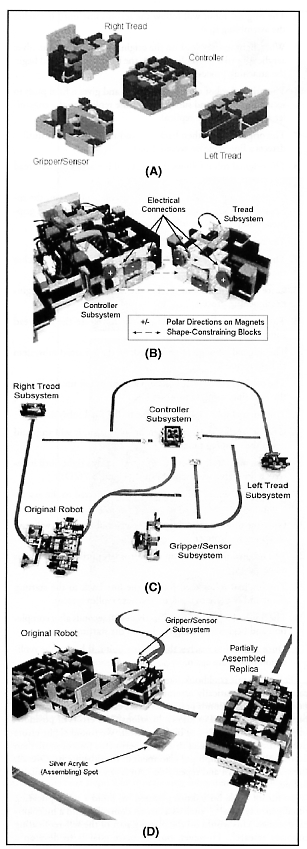
Figure 3.76. LEGO®-based fully-autonomous kinematic replicator...171 (and caption)
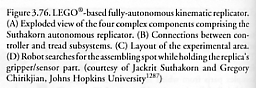
Figure 3.77. Architecture for self-replication...174
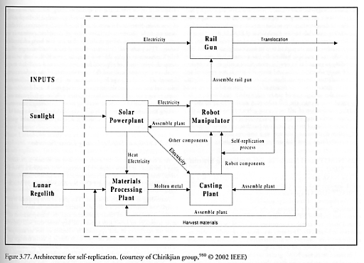
Figure 3.78. Depiction of the functioning lunar self-replicating factory...174
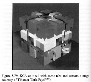
Figure 3.79. KCA unit cell with some tabs and sensors...180
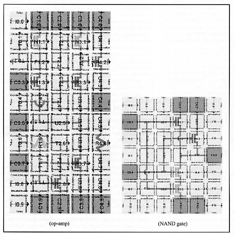
Figure 3.80. Wang-tile implementations of an op-amp and a NAND gate, using KCA cells configured as electronic wire/transistor components...181 (and caption)
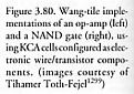
Figure 3.81. Two steps among many, in a lengthy parts assembly operation involving KCA cells on a base plane platform...181
Figure 3.82. Robosphere 2002 workshop on self-sustaining robotic ecologies...182
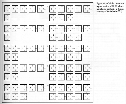
Figure 3.83. Cellular automaton representation of Griffith linear templating replication...185
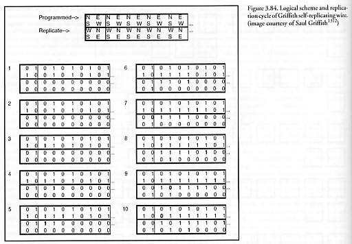
Figure 3.84. Logical scheme and replication cycle of Griffith self-replicating wire...187
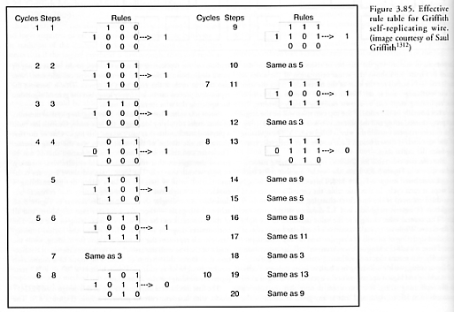
Figure 3.85. Effective rule table for Griffith self-replicating wire...188
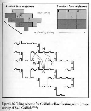
Figure 3.86. Tiling scheme for Griffith self-replicating wire...189
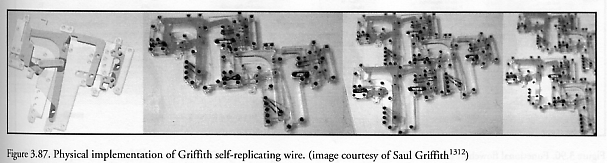
Figure 3.87. Physical implementation of Griffith self-replicating wire...190
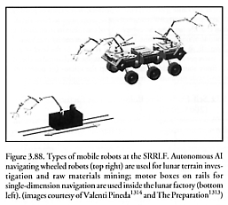
Figure 3.88. Types of mobile robots at the SRRLF...191
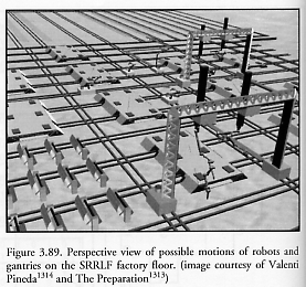
Figure 3.89. Perspective view of possible motions of robots and gantries on the SRRLF factory floor...191
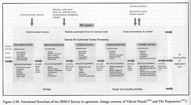
Figure 3.90. Functional flowchart of the SRRLF factory in operation...192
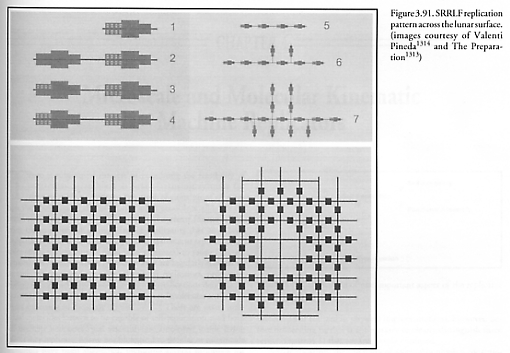
Figure 3.91. SRRLF replication pattern across the lunar surface...193
Chapter 4. Microscale and Molecular Kinematic Machine Replicators
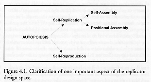
Figure 4.1. Clarification of one important aspect of the replicator design space...195
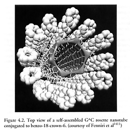
Figure 4.2. Top view of a self-assembled G^C rosette nanotube conjugated to benzo-18-crown-6...200
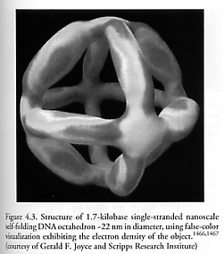
Figure 4.3. Structure of 1.7-kilobase single-stranded nanoscale self-folding DNA octahedron...203
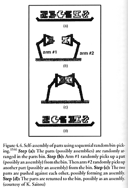
Figure 4.4. Self-assembly of parts using sequential random bin-picking...206
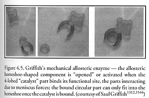
Figure 4.5. Griffith’s mechanical allosteric enzyme...207
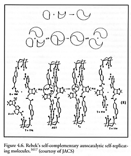
Figure 4.6. Rebek’s self-complementary autocatalytic self-replicating molecules...210
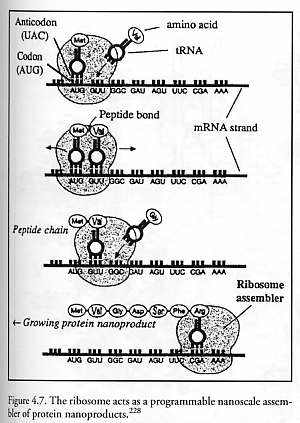
Figure 4.7. The ribosome acts as a programmable nanoscale assembler of protein nanoproducts...212
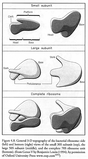
Figure 4.8. General 3-D topography of the bacterial ribosome: side and bottom views of the small 30S subunit, the large 50S subunit, and the complete 70S ribosome unit...213
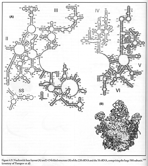
Figure 4.9. Nucleotide base layout and 3-D folded structure of the 23S rRNA and the 5S rRNA, comprising the large 50S subunit...214
Figure 4.10. Nucleotide base layout and 3-D folded structure of the 16S rRNA, comprising the small 30S subunit...215
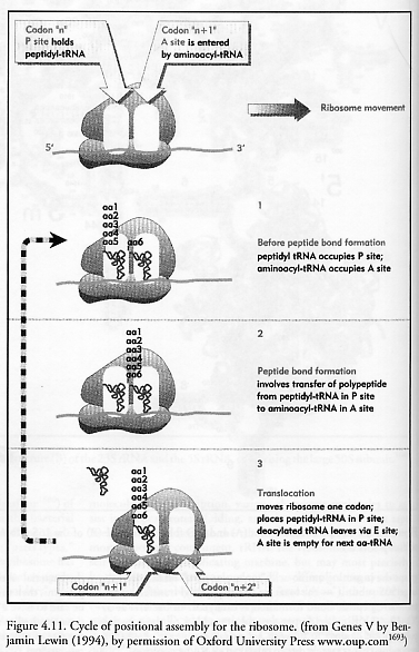
Figure 4.11. Cycle of positional assembly for the ribosome...216
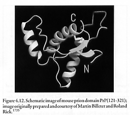
Figure 4.12. Schematic image of mouse prion domain PrP(121-321)...219
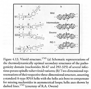
Figure 4.13. Viroid 3-dimensional structure...220
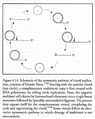
Figure 4.14. Schematic of viroid replication...220
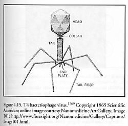
Figure 4.15. T4 bacteriophage virus...223
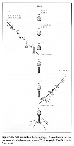
Figure 4.16. Self-assembly of bacteriophage T4 in ordered sequence from its individual component parts...223
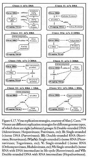
Figure 4.17. Virus replication strategies...224
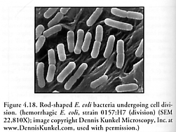
Figure 4.18. Rod-shaped E. coli bacteria undergoing cell division...226
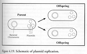
Figure 4.19. Schematic of plasmid replication...228
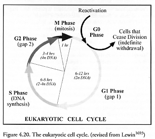
Figure 4.20. The eukaryotic cell cycle...229
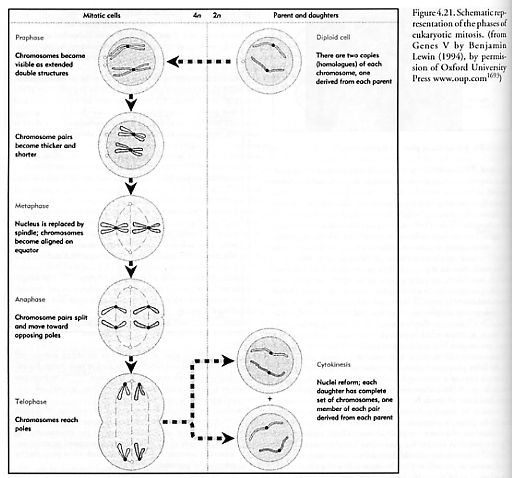
Figure 4.21. Schematic representation of the phases of eukaryotic mitosis...230
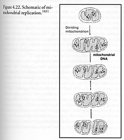
Figure 4.22. Schematic of mitochondrial replication...232
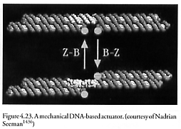
Figure 4.23. A mechanical DNA-based actuator...240
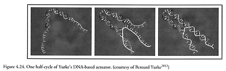
Figure 4.24. One half-cycle of Yurke’s DNA-based actuator...242
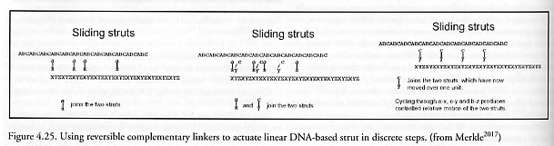
Figure 4.25. Using reversible complementary linkers to actuate linear DNA-based strut in discrete steps...242
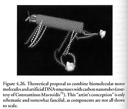
Figure 4.26. Theoretical proposal to combine biomolecular motor molecules and artificial DNA structures with carbon nanotubes...243
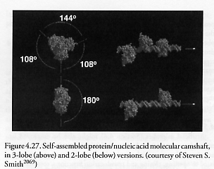
Figure 4.27. Self-assembled protein/nucleic acid molecular camshaft, in 3-lobe and 2-lobe versions...244
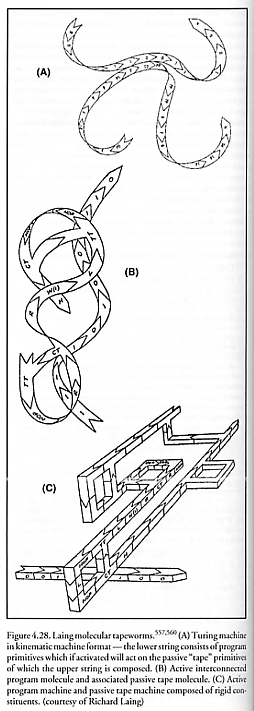
Figure 4.28. Laing molecular tapeworms...255
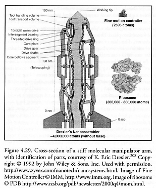
Figure 4.29. Cross-section of a stiff molecular manipulator arm, with identification of parts; image of Fine Motion Control; image of ribosome...258
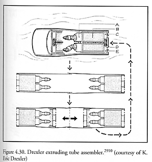
Figure 4.30. Drexler extruding tube assembler...260
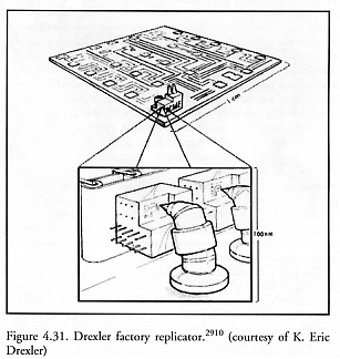
Figure 4.31. Drexler factory replicator...262
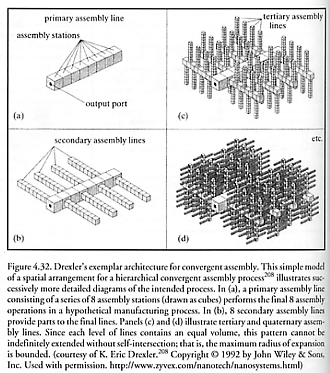
Figure 4.32. Drexler’s exemplar architecture for convergent assembly...263
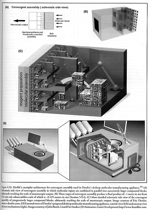
Figure 4.33. Merkle’s exemplar architecture for convergent assembly used in Drexler’s desktop molecular manufacturing appliance...264
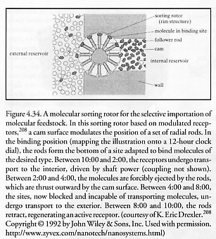
Figure 4.34. A molecular sorting rotor for the selective importation of molecular feedstock...266
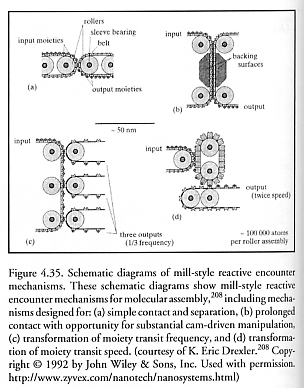
Figure 4.35. Schematic diagrams of mill-style reactive encounter mechanisms...266
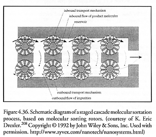
Figure 4.36. Schematic diagram of a staged cascade molecular sortation process, based on molecular sorting rotors...269
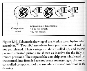
Figure 4.37. Schematic drawing of the Merkle cased hydrocarbon assembler...270
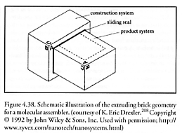
Figure 4.38. Schematic illustration of the extruding brick geometry for a molecular assembler...273
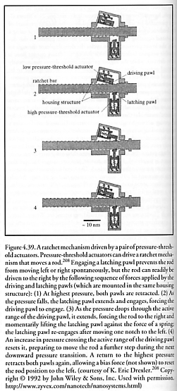
Figure 4.39. A ratchet mechanism driven by a pair of pressure-threshold actuators...275
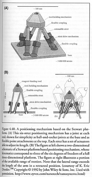
Figure 4.40. A positioning mechanism based on the Stewart platform...276
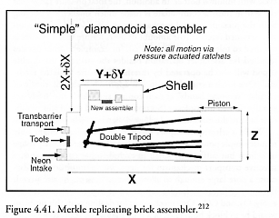
Figure 4.41. Merkle replicating brick assembler...277
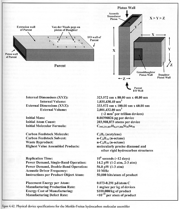
Figure 4.42. Physical device specifications for Merkle-Freitas hydrocarbon molecular assembler...280
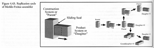
Figure 4.43. Replication cycle of Merkle-Freitas assembler...282
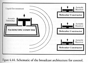
Figure 4.44. Schematic of the broadcast architecture for control...283
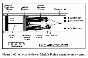
Figure 4.45. Schematic view of Merkle-Freitas assembler subsystems...285
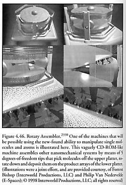
Figure 4.46. Rotary assembler...290
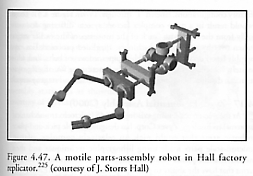
Figure 4.47. A motile parts-assembly robot in Hall factory replicator...292
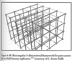
Figure 4.48. Rectangular 3-dimensional framework for parts assembly in Hall factory replicator...292
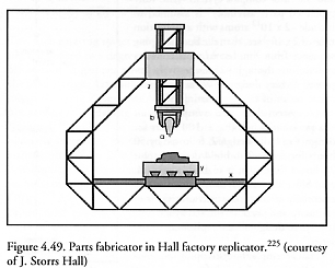
Figure 4.49. Parts fabricator in Hall factory replicator...293
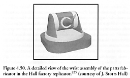
Figure 4.50. A detailed view of the wrist assembly of the parts fabricator in the Hall factory replicator...293
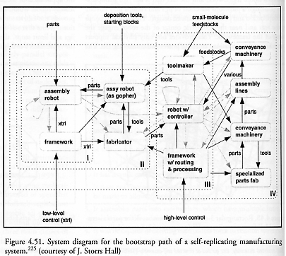
Figure 4.51. System diagram for the bootstrap path of a self-replicating manufacturing system...294
Figure 4.52. Basic two-component RotapodTM assembly station...295
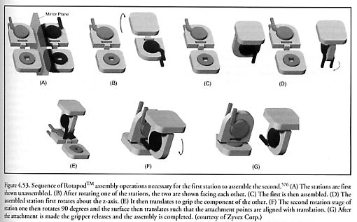
Figure 4.53. Sequence of RotapodTM assembly operations necessary for the first station to assemble the second...296
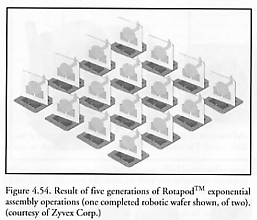
Figure 4.54. Result of five generations of RotapodTM exponential assembly operations...297
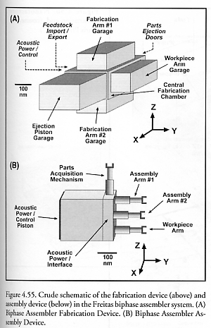
Figure 4.55. Crude schematic of the fabrication device and assembly device in the Freitas biphase assembler system...299
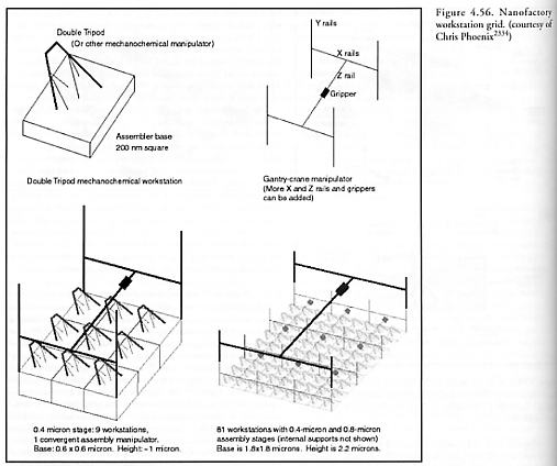
Figure 4.56. Nanofactory workstation grid...302
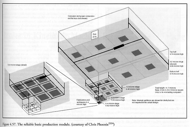
Figure 4.57. The reliable basic production module...302
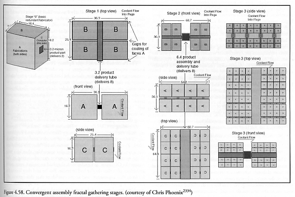
Figure 4.58. Convergent assembly fractal gathering stages...303
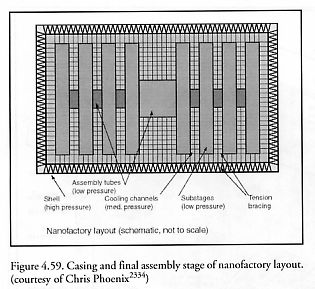
Figure 4.59. Casing and final assembly stage of nanofactory layout...304
Chapter 5. Issues in Kinematic Machine Replication Engineering
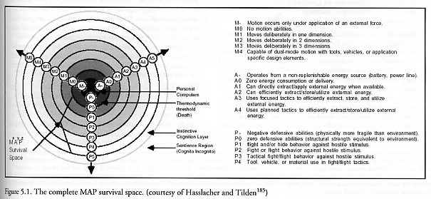
Figure 5.1. The complete MAP survival space...312
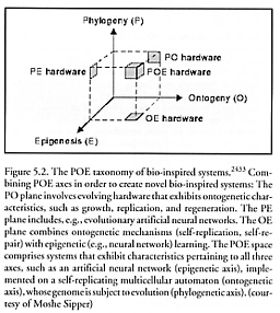
Figure 5.2. The POE taxonomy of bio-inspired systems...316
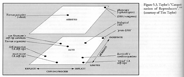
Figure 5.3. Taylor’s “Categorization of Reproducers”...317
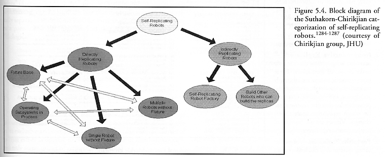
Figure 5.4. Block diagram of the Suthakorn-Chirikjian categorization of self-replicating robots...320
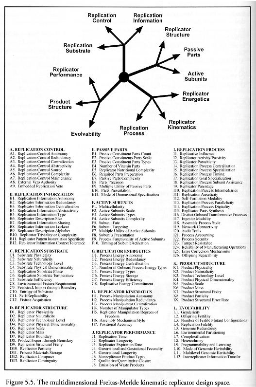
Figure 5.5. The multidimensional Freitas-Merkle kinematic replicator design space...322
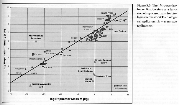
Figure 5.6. The 1/4-power law for replication time as a function of replicator mass, for biological replicators...368
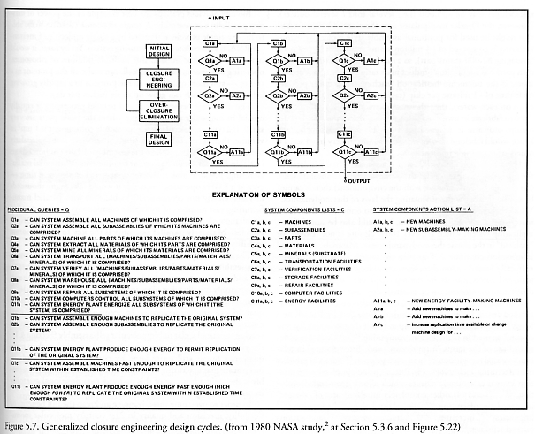
Figure 5.7. Generalized closure engineering design cycles...379
Figure 5.8. Millipede concept of IBM Zurich Research Laboratory...383
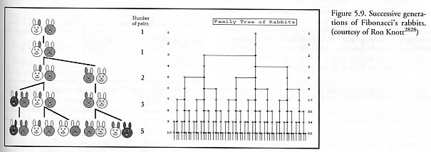
Figure 5.9. Successive generations of Fibonacci’s rabbits...387
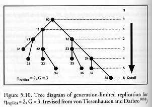
Figure 5.10. Tree diagram of generation-limited replication for hreplica = 2, G = 3...394
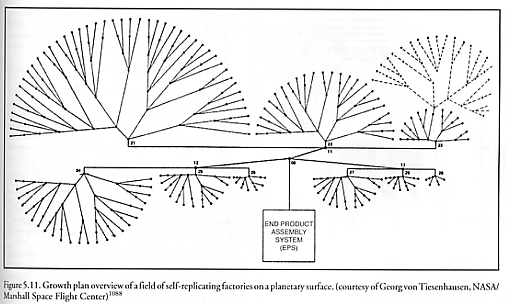
Figure 5.11. Growth plan overview of a field of self-replicating factories on a planetary surface...395
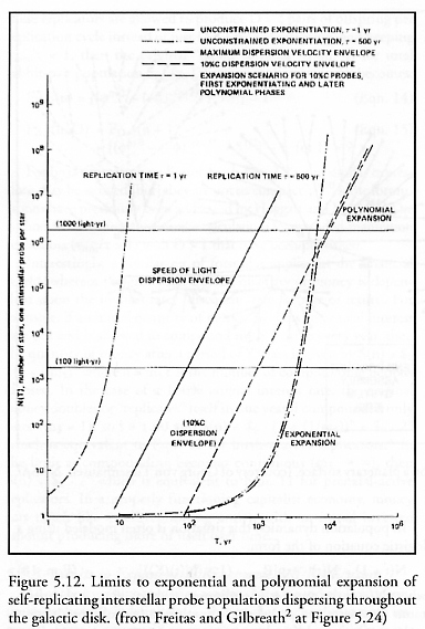
Figure 5.12. Limits to exponential and polynomial expansion of self-replicating interstellar probe populations dispersing throughout the galactic disk...396
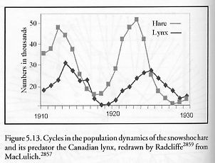
Figure 5.13. Cycles in the population dynamics of the snowshoe hare and its predator the Canadian lynx...398
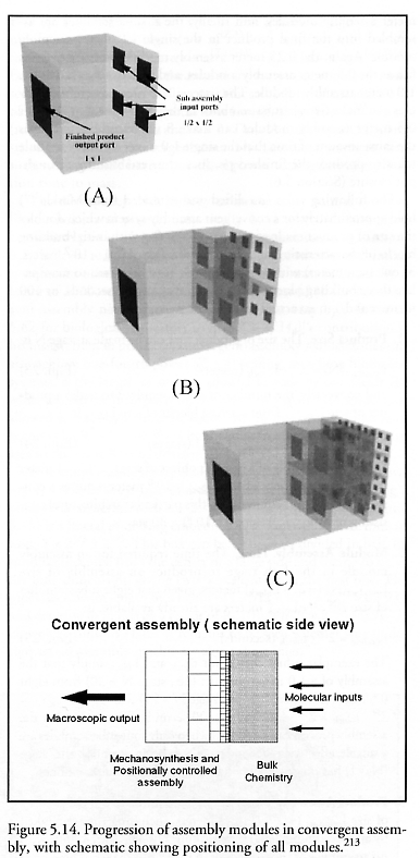
Figure 5.14. Progression of assembly modules in convergent assembly, with schematic showing positioning of all modules...400
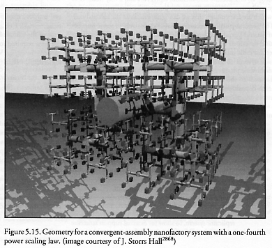
Figure 5.15. Geometry for a convergent-assembly nanofactory system with a one-fourth power scaling law...405
Appendix B. Design Notes on Some Aspects of the Merkle-Freitas
Molecular Assembler
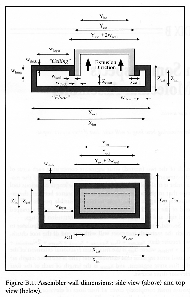
Figure B.1. Assembler wall dimensions: side view and top view...457
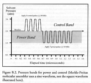
Figure B.2. Pressure bands for power and control...465
Last updated on 1 August 2005